
Cisco Configuration Notes
Page Listing:
- Cisco Terminal Connection
- Basic Navigation
- Switch Initial Setup
- Switch Security (Passwords)
- Switch Security - Turn on SSH
- Switch Security - Port Security
- #More Configuration and Show Commands
- Router Configuration - Basics
- Security Device Manager (SDM) - GUI Management
- Static IP Routing
- Dynamic IP Routing - Example RIPv2
- Serial Connection between Routers
- Cisco Discovery Protocol (CDP)
- Network Address Translation (NAT)
- tftp server notes
- VLANs - an example
- Spanning Tree Protocol (STP)
- Frame Relay ( Point To Point )
Cisco Terminal Connection
Cisco usually provides a Console interface Cable with their switches and routers
This cable is used to connect your PC to the Console port on the back of the Cisco unit
A Terminal emulation application is required to configure and use the interface
A good terminal emulation utility is: TERA TERM
Port Configuration values are as follows:
|
com port (usually): |
1 |
|
Baud Rate: |
9600 |
|
Data bits: |
8 |
|
Parity: |
NONE |
|
Stop bits: |
1 |
|
Flow Control: |
NONE |
* Home
Basic Navigation
Cisco devices, Internetwork Operating System (IOS), have three main modes of operation, these modes and some basic navigation techniques are given below
Basic Navigation Cisco Devices
|
User Mode: |
This is the default mode with limited functionality Limited Show commands, ping or telnet functionality only The IOS Prompt looks like: switchname > |
|
Privileged Mode: |
Enables Full Configuration visabilty Shows all configuration and status details including password details From User Mode type: enable to go to Privileged Mode The IOS Prompt looks like: switchname # |
|
Global Configuration Mode: |
Enables global Configuration options User can change any global configurations from this prompt From Privileged Mode type configure terminal to enter global configuration using the console terminal port The IOS Prompt looks like: switchname(config) # From the Global Configuration prompt, hundreds of other configuration modes are available As a potential example type: interface fastEthernet 0/1 The IOS Prompt will change to: switchname(config-if) # |
|
end exit ctrl z |
Use these commands to exist a particular mode end go back to privileged mode exit move back to previous level mode ctrl z takes you out of the current mode |
|
? |
Use the question mark to get a list of available commands at the current mode and if you are uncertain of what to type next for a given command |
|
tab |
Use the tab key to complete partially entered commands |
|
no command |
Use no and the command to undo or revert back from a command (to undo a command) |
|
show history |
To see previous commands |
|
ctrl a ctrl e |
ctrl a to go to the beginning of the command line ctrl e to go to the end of the command line |
* Home
Switch Initial Setup
Follow these initial setup instructions along with the Switch Password Security instructions using your PC connected to the console port located at the back of new switch. These instructions will then allow remote telnet access to the switch from a host connected to a port at the front of the switch for further switch configuration and management
There is no power button. The switch will load the IOS when the switch is plugged in. A lot of system data is displayed to the screen. Eventually you will be prompted with:
Would you like to enter the initial configuration dialog? [yes/no]:
Answer noBecause of all the system data being displayed, you may have to hit enter a couple of time to re-print the above dialog
If you end up in autoconfguration mode press ctrl c to exit
The initial startup IOS prompt looks like:
Switch >
type enable to go to privileged mode
The prompt looks like:
Switch #
type configure terminal to go to global configuration mode
The prompt looks like:
Switch(config) #
type hostname MySwitch to give the switch a hostname
The prompt looks like:
MySwitch(config) #
It is recommended the Switch is given a meaningful hostname.
Perhaps signifying its location. For example: Rack1_S1
type interface vlan 1 to enter VLAN 1 configuration mode
The prompt looks like:
MySwitch(config-if) #
type ipaddress 192.1.1.1 255.255.255.0 to set VLAN IP and sub-mask
A new switch has only one VLAN. The IP address is a virtual IP address.
It is not assigned to any port, but to the switch (VLAN) as a whole.
It allows Telnet or pings to the switch by any host connected to the VLAN.
The interface is adminstratively down at this time
type no shutdown to bring the interface up
The status of the interface can be checked from the privileged mode
type end to exit configuration and go to privilege mode
The prompt looks like: MySwitch #
type show interface vlan 1 to show VLAN 1 status details
Next set the default gateway
The default-gateway is a global configuration
type configure terminal to go to global configuration mode
The prompt looks like:
MySwitch(config) #
type default-gateway 192.1.1.10 to set the default gateway
type end to exit configuration and go to privilege mode
The prompt looks like: MySwitch #
type show running-config to see all typed commands and default commands
type copy running-config startup-config to save configuration changes
You will be prompted with
Destination filename [startup-config]?
Hit the enter key. Do NOT type anything, such as "y", otherwise
the configuration will be saved to a file with that name
The new configuration is now available in NVRAM should the switch be rebooted.
* Home
Switch Security (Passwords)
The Best security for your Switches is physical security. In other words, do not allow unauthorised access to them. Ensure your communication room and operational areas are secure
The following commands are entered in global configuration mode. See above for details
c1sco (spelt with a "1") is the generic password used in these examples
Protect privileged mode
|
|
|
|
enable password c1sco |
This is a legacy method This password is in plain text in the running-config |
|
enable secret c2sco |
This is a better method to secure access to the privileged mode This command supersedes the above command. So if you have used both, make sure the passwords are different This password is encrypted (level7) in the running-config The encryption used is easily broken. |
Protect Console Access
|
|
|
|
line console 0 login password c1sco |
IOS Prompt changes to: Myswitch(config-line) # This sets login Set the password |
Protect Telnet Access
By default, telnet login to the switch is not enabled. Telnet net access is through virtual ports (vty)
If you check the running-config, you will see a login statement against the vty ports. This indicates
login is required
You will also have an indication of how my vty (virtual ports) are available. By setting the passwords
for the first two ( 0 and 1 ), as shown, we are limiting telnet access to two sessions that both require passwords
Starting in global config mode
|
|
|
|
line vty 0 1 login password c1sco |
IOS Prompt changes to: Myswitch(config-line) # This sets login Set the password |
Encrypted all Passwords
Starting in global config mode
|
|
|
|
service password-encryption |
Check passwords in running-config |
* Home
Switch Security - Turn on SSH
Secure Shell (SSH) is a secure form of telnet. It ensures packet sniffers, such as, wireshark cannot be used to read session data
Starting in global config mode
|
|
|
|
username cottage password c1sco ip domain-name cottageviews.co.uk crypto key generate rsa general-keys 1024 ip ssh version 2 line vty 0 1 transport input telnet ssh |
Where cottage is the user name and C1sco the password The Domain name is used to generate encryption certificate This is to enable both telnet and SSH (could also just type all) |
* Home
Switch Security - Port Security
Use port security if you want to ensure only specific devices are plugged to specific ports. Setting port security creates a lot of administrative overhead as the switch configuration will have to be changed if devices are changed
Note: See useful show commands below when configuring port security
Note: You can configure multiple ports at once by changing the first command below to:
interface range fastEthernet 0/2 - 24 (this will affect ports 2 through 24)
To do this ensure all appropriate devices are plugged into the switch first so the sticky option can be used - see below
Starting in global config mode
|
|
|
|
interface fastEthernet 0/2 switchport mode access switchport port-security switchport port-security maximum 1 switchport port-security violation shutdown switchport port-security mac-address sticky |
Go to the desired interface (mode) to configure Ensures port is connected to a device (not another switch) Sets port security with default values if a device is connected Ensures only one device on this port Port is shut-down if security violation Use sticky if device is plugged into the port |
* Home
More Configuration and Show Commands
While setting port security for all the ports, it is also a good idea to set the mode and speed of operation
While in the Global configuration Mode:
At the global config mode
|
|
|
|
interface range fastEthernet 0/2 - 24 duplex full speed 100 exit |
To configure port 2 through 24 Set to full duplex Set speed to 100 Mbps Note: Almost all Devices, such as hosts and servers, |
At the global config mode
|
|
|
|
line con 0 exec-timeout 30 0 exit line vty 0 4 exec-timeout 30 0 exit line con 0 logging synchronous exit line vty 0 4 logging synchronous exit |
Set session timeout for console connects to 30 minutes and zero seconds Set session timeout for telnet connects to 30 minutes and zero seconds This helps when system message write over you command entries With this set, your command entry will be repeat |
Useful Show Commands
Note show commands can be executed from the Configuration modes by using the do command.
For example:
do show run interface fastEthernet 0/2
In Privilege Mode
|
|
|
|
terminal monitor Show ip interface brief Show interface fastethernet 0/2 show mac address-table show sessions
show users
alias exec b show ip interface brief |
Lets you see all switch messages (i.e. status changes) Shows briefly all ports interface status Shows status of a specific port Shows static and dynamic mac addresses To see open sessions from your router To see open sessions to your router Sets b as an alias for "show ip interface brief" |
* Home
Router Configuration - Basics
The configuration notes above can be followed in the initial configuration of a router. Routers come in various sizes and configurations depending on user requirements and the supplied modules.
In this basic example we look at a simple four Ethernet switch port (0...3) router with a single Ethernet WAN interface (4). You may need to look at the back of the router to determine which Ethernet port is the WAN interface.
|
|
WAN interface configuration In Global configuration mode, type: Switch LAN interfaces configuration For completeness here, the VTY (Telnet) access from the other Ethernet switch LAN ports can be configured as follows 192.168.1.1 255.255.255.0 exit interface range fastethernet 0 - 3 no shutdown To see port status details |
* Home
Security Device Manager (SDM) - GUI Management
Cisco's Security Device Manager (SDM) provide GUI based configuration management, security management, and operational monitoring of your Cisco Router devices.
It is shipped in flash memory on most main stream Cisco routers, and it can be downloaded for the Cisco Web Site. It can be installed and operated from both the Cisco router or your PC. Your PC will need Java installed in order to support SDM. The advantages of running from your PC include the ability to manage multiple cisco routers from one location, and also faster performance.
In order to use SDM you will have to generate encryption keys; and enable SSH; and create a user for console access and the VTY ports as described above for switch configuration.
In additions, Support for HTTP and HTTPS will have to be enabled on the Cisco Router.
To do this this type the following while in the Global configuration mode:
ip http server
ip http secure-server
username cottage privilege 15 secret c1sco // create secure user account with user name cottage and password c1sco
ip http authentication local
line vty 0 4 // assuming 4 VTY ports
login local
exit // Note: If you change the hostname or domain name the enscryption keys will have to be regenerated- See SSH configuration above
After installing SDM on your PC, you can now use SDM to complete the configuration of the Router including the set-up of DHCP
Note: To see all commands before they are sent to the router, from the SDM GUI select the following:
EDIT, PREFERENCES and TICK - "Preview commands before delivering to router"
* Home
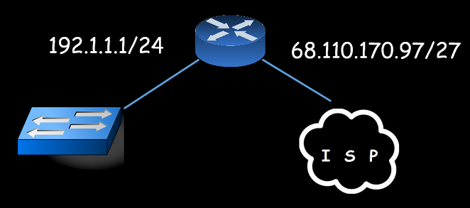
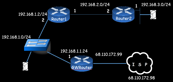
Static IP Routing
Two examples of Static IP routing is described here. The first is for Intranet routing between routers on the same intranet. The second example is to route to the internet (or the internet service provider (ISP))
Note: Although routing to the ISP is configured here, hosts will NOT be able to connect to the internet until Network Address translation (NAT) is set up because they are using private Class C IP addresses. Please refer to Default IP Address Classes for further details
|
|
Intranet Routing In Global configuration mode - Router 1, type: In Global configuration mode - Router 2, type: Internet ISP Routing In Global configuration mode - GWRouter, type: Additionally on the GWRouter so it can talk to devices connected to Router 2 Other Configuration commands show run | include ip route Note:This shows the ip routes in the running configuration You can then delete them by putting a no in front of the commands Also to see route status details use: |
* Home
Dynamic IP Routing - Example RIPv2
There are three types of dynamic routing
Distance Vector
This is the easiest to implement. Examples include:
RIPv1
Does not support variable lenght subnet masks (VLSM)
No Authenication is required, and it uses broadcast.
This means unauthorised routers can be added to your network,
and broadcasting uses up more bandwidth
RIPv2
Supports variable lenght subnet masks (VLSM)
Authenication is required, and it uses unicast.
Only configured RIP routers received updates
and broadcasting uses up more bandwidth
Link State
This is more complex to implement, but provides better routing. Examples include:
OSPF
IS-IS
Hybrid
Provides the best of both options. Examples include:
EIGRP
This is a Cisco proprietary routing protocol
The below shows how to implement RIPv2 on the three routers shown in the above diagram
|
RIP Version 2 example In Global configuration mode - GWRouter, type: In Global configuration mode - Router 2, type: In Global configuration mode - Router 1, type: Other useful commands On the GWRouter Other useful commands |
* Home
Serial Connection between Routers
PPP and HDLC protocols are commonly used betwenn routers within an organization. HDLC is a Cisco proprietary protocol.
When setting up a serial connection between two routers, one router has to be set-up as a DCE and the other router has to be set up as a DTE. The cable, for the serial link between the routers, must reflect this requirement
Example DCE router configuration
In Global configuration mode
interface serial 0/0
encapsulation ppp // HDLC Cisco propietary also an option
clock 153600 // use " ? " to see available clock speeds
Example DTE router configuration
In Global configuration mode
interface serial 0/0
encapsulation ppp // HDLC Cisco propietary also an option
Useful Commands
show ip interface brief
show interface serial 0/0
show controllers serial 0/0 // See DTE/DCE details and clock rate
* Home
Cisco Discovery Protocol (CDP)
Use Cisco Discovery Protocol (CDP) to build up a network diagram of your network.
Useful Command
show ip interface brief
show cdp neighbors
show cdp entry router3 // To see details about a connected router
show cdp entry * // To see details of all connected cisco devices
show cdp detail
To turn off CDP
In Global configuration mode
no cdp enable // Do this perhaps for security reasons
no cdp run
* Home
Network Address Translation (NAT)
NAT allows multiple devices to share an IP address. NAT has to be set-up before the devices on your Intranet can access the Internet
The easiest way of setting up NAT is using the SDM.
With SDM connected to the GWRouter
Select Configure and then NAT
You are given two options. Basic and Advanced
Select Basic and follow the Wizard if your devices only need internet Access
This option used Port Address Translation (PAT).
Select Advanced and follow the Wizard if you have Servers that will be accessed from the Internet. This option uses Static IP addresses to support your Servers.
Useful Commands
show ip nat translations
* Home
tftp server notes
There are a number of "tftp server" options that can be installed on a designated tftp server host. A popular option is tftp32 .
Copy the running configuration to the tftp server as follows
On the router - type
copy running-config tftp // And follow the prompts
* Home
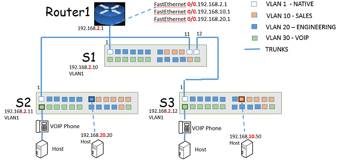
VLANs - an example
Please refer to the below diagram for this example. We connect three switches and a Router using trunk ports. These switches will support three VLANs. The native VLAN 1 ( us for trunk ports) and two additional VLANs, VLAN 10 and VLAN 20. Colour codes are used to indicate that VLANs can span multiple switches depending on configuration requirements. Configuration of port 7 on S2 and port 8 on S3 are described below. Static IP addresses have been assigned on these hosts.
VLANs should be considered as broadcast domains or sub-nets. For simplicity here, we are using the third octet of the IP address for the subnets.
The three sub-networks are:
192.168.2.0 /24 - VLAN 1 (native VLAN) with the default gateway of 192.168.2.1
192.168.10.0 /24 - VLAN 10 with the default gateway of 192.168.10.1
192.168.20.0 /24 - VLAN 20 with the default gateway of 192.168.20.1
Further details on subnetting can be found here.
The protocol used on the trunks is 802.1Q which allows the trunks to pass the configured VLAN traffic.
VTP is used to replicate VLAN information between the switches. It works only over the TRUNK interfaces (VLAN 1 in this instance). S1 is configured as a VTP server and the other two switches as VTP clients. Once VTP is configured, VLAN configuration should be done on S1 and this information is then automatically replicated to the other two switches.
The VLAN routing method described here is known as "Router on a stick". It is probably the most common method. Some, more expensive routers, support VLAN routing from within the switch, and another option is to run a separate fastethernet link for each VLAN to the router and configure routing between the interfaces at the router.
Step 1 - Configuring the Trunks
On S1 in global configuration
interface fastethernet 0/11
switchport trunk encapsulation dot1q // This may not be necessary if only 802.1Q is supported
switchport mode trunk
exit
interface fastethernet 0/12
switchport trunk encapsulation dot1q // This may not be necessary if only 802.1Q is supported
switchport mode trunk
exit
interface range fastethernet 0/1 - 10
switchport mode access // set all the other ports to access - for hosts
interface range fastEthernet 0/13 - 24
switchport mode access
On S2 in global configuration
interface fastethernet 0/1
switchport mode trunk
interface range fastEthernet 0/2 - 24
switchport mode access
On S3 in global configuration
interface fastethernet 0/1
switchport mode trunk
interface range fastEthernet 0/2 - 24
switchport mode access
Step 2 - Configuring VTP
Note: Switches are configured as VTP Servers by default. So VLAN/VTP configuration changes will automatically replicate to the other switches until they are configured as VTP Clients.
On S1 in global configuration // Note: Defaults is VTP Server
vtp domain COTTAGEVIEWS
vtp password c1sco
vlan 10
name SALES
exit
vlan 20
name ENGINEERING
exit
interface fastethernet 0/1
switchport mode trunk // For Router on a stick
On S2 in global configuration
vtp mode client // Set S2 as VTP client
interface fastethernet 0/7
switchport access vlan 20 // Assign port 7 to VLAN 20
exit
On S3 in global configuration
vtp mode client // Set S3 as VTP client
interface fastethernet 0/8
switchport access vlan 10 // Assign port 8 to VLAN 10
exit
Step 3 - Configuring Router on a Stick
On Router1 in global configuration
interface fastethernet 0/0.10
encapsulation dot1Q 10
ip address 192.168.10.1 255.255.255.0
exit
interface fastethernet 0/0.20
encapsulation dot1Q 20
ip address 192.168.20.1 255.255.255.0
exit
Note: VLAN 1 (the native VLAN) is already configured
Useful Show Commands
show ip interface brief
show vtp status
show vlan
show interfaces trunk
show ip route // on the router to see what routes it knows
show interfaces fastethernet 0/1 switchport // switch port mode characteristics
Note: To completely flush VLAN and VTP information so you can re-configure a switch use:
delete flash:\VLAN.DAT // execute in privileged mode
Note: VLAN information is not shown in the running config
* Home
Spanning Tree Protocol (STP)
Spanning Tree Protocol (STP) is used to stop "Broadcast storms" because of loops caused by redundant links between switches. It is NOT a router protocol
The Original STP protocol is 802.1D. It takes almost a minute for a switch-over from the primary link to the redundant link using this protocol (should the primary link go down). 802.1W has been introduced to be more proactive (faster) in the switch-over, but it requires more overhead in configuration.
Please refer to the diagram describing VLANs above and imagine a redundant link between S2 and S3.
STP is turned on by default and functions automatically, but the primary root switch for STP, by default, is the switch with the oldest MAC address.
To enable STP with S1 assigned as primary core root switch, do the following:
On S1 in global configurationSpanning-tree vlan 1 root primary
Or
Spanning-tree vlan 1,10, 20 root primary
Note: You can set different primary and redundant links for different VLANs by executing the above commands per VLAN on the different switches. This is useful for load-sharing or to ensure that redundant links do get some traffic activity
To enable Rapid STP (RSTP) 802.1.W, The below configuration command has to be executed on ALL the switches
In global configuration mode:
spanning-tree mode rapid-pvst
and, this configuration command has to be executed on all the access (devices) ports:
In interface configuration mode for all ports with device access:
spanning-tree portfast // on access ports only for hosts and devices
spanning-tree bpduguard // This is to ensure no switches can be added to this port
Useful Show Commands
show spanning-tree* Home
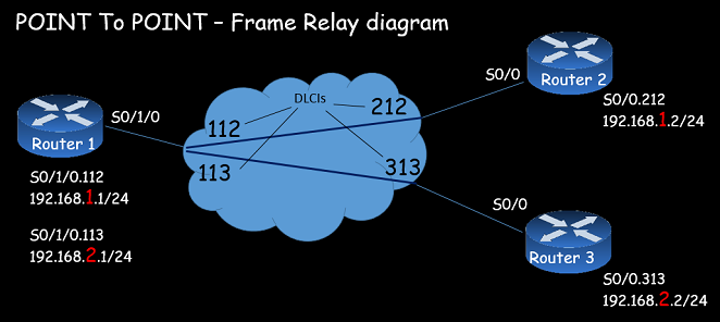
Frame Relay ( Point To Point )
The two approaches to implementing Frame Relay are "Multi-Point Design" and "Point to Point Design".
For multi-point design, all of the router interfaces are on the same sub-net. This may cause issues with split-horizons which prohibits boardcasts down the same interface (split-horizon has to be disabled). multi-point is also more complex to configure.
Point to Point design require router interfaces to be on their own sub-net. Routing protocols such as OSPF, EIGRP or RIP V2 will often discover routing neighbors using this method making configuration easier.
|
|
Router 1 Congiguration In Global configuration mode - Router 1, type: Router 2 Congiguration In Global configuration mode - Router 2, type: Router 3 Congiguration In Global configuration mode - Router 3, type: A configured routing protocol will advertise the connecting links Useful Show Commands show frame-relay lmi // frame-relay management language used - and further detailsshow frame-relay map show frame-relay pvc show ip interface brief |